|
SECTION
909 SMOKE CONTROL SYSTEMS
[F] 909.1 Scope and purpose.
This section applies to mechanical or passive smoke control
systems when they are required by other provisions of this
code. The purpose of this section is to establish minimum
requirements for the design, installation and acceptance testing
of smoke control systems that are intended to provide a tenable
environment for the evacuation or relocation of occupants.
These provisions are not intended for the preservation of
contents, the timely restoration of operations or for assistance
in fire suppression or overhaul activities. Smoke control
systems regulated by this section serve a different purpose
than the smoke- and heat - venting provisions found in Section
910. Mechanical smoke control systems shall not be considered
exhaust systems under Chapter 5 of the International Mechanical
Code.
[F] 909.2 General design requirements.
Buildings, structures or parts thereof required by this code
to have a smoke control system or systems shall have such
systems designed in accordance with the applicable requirements
of Section 909 and the generally accepted and well-established
principles of engineering relevant to the design. The construction
documents shall include sufficient information and detail
to adequately describe the elements of the design necessary
for the proper implementation of the smoke control systems.
These documents shall be accompanied by sufficient information
and analysis to demonstrate compliance with these provisions.
[F] 909.3 Special inspection
and test requirements. In addition to the ordinary inspection
and test requirements which buildings, structures and parts
thereof are required to undergo, smoke control systems subject
to the provisions of Section 909 shall undergo special inspections
and tests sufficient to verify the proper commissioning of
the smoke control design in its final installed condition.
The design submission accompanying the construction documents
shall clearly detail procedures and methods to be used and
the items subject to such inspections and tests. Such commissioning
shall be in accordance with generally accepted engineering
practice and, where possible, based on published standards
for the particular testing involved. The special inspections
and tests required by this section shall be conducted under
the same terms in Section 1704.
[F] 909.4 Analysis. A
rational analysis supporting the types of smoke control systems
to be employed, their methods of operation, the systems supporting
them and the methods of construction to be utilized shall
accompany the submitted construction documents and shall include,
but not be limited to, the items indicated in Sections 909.4.1
through 909.4.6.
[F]
909.4.1 Stack effect. The system shall be designed such
that the maximum probable normal or reverse stack effect
will not adversely interfere with the system's capabilities.
In determining the maximum probable stack effect, altitude,
elevation, weather history and interior temperatures shall
be used.
[F]
909.4.2 Temperature effect of fire. Buoyancy and expansion
caused by the design fire in accordance with Section 909.9
shall be analyzed. The system shall be designed such that
these effects do not adversely interfere with the system's
capabilities.
[F]
909.4.3 Wind effect. The design shall consider the adverse
effects of wind. Such consideration shall be consistent
with the wind-loading provisions of Chapter 16.
[F]
909.4.4 HVAC systems. The design shall consider the
effects of the heating, ventilating and air-conditioning
(HVAC) systems on both smoke and fire transport. The analysis
shall include all permutations of systems status. The design
shall consider the effects of the fire on the HVAC systems.
[F]
909.4.5 Climate. The design shall consider the effects
of low temperatures on systems, property and occupants.
Air inlets and exhausts shall be located so as to prevent
snow or ice blockage.
[F]
909.4.6 Duration of operation. All portions of active
or passive smoke control systems shall be capable of continued
operation after detection of the fire event for a period
of not less than either 20 minutes or 1.5 times the calculated
egress time, whichever is less.
[F]
909.5 Smoke barrier construction. Smoke barriers shall
comply with Section 709, and shall be
constructed and sealed to limit leakage areas exclusive of
protected openings. The maximum allowable leakage area shall
be the aggregate area calculated using the following leakage
area ratios:
1. Walls: A/Aw
= 0.00100
2. Exit enclosures:
A/Aw = 0.00035
3. All other shafts:
A/Aw = 0.00150
4. Floors and roofs:
A/Aw = 0.00050
where:
A =
Total leakage area, square feet (m2),
AF =
Unit floor or roof area of barrier, square feet (rn2).
Aw =
Unit wall area of barrier, square feet (m2),
The leakage area ratios
shown do not include openings due to doors, operable
windows or similar gaps. These shall be included in
calculating the total leakage area.
[F]
909.5.1 Leakage area. The total leakage area of the
barrier is the product of the smoke barrier gross area multiplied
by the allowable leakage area ratio, plus the area of other
openings such as gaps and operable windows. Compliance shall
be determined by achieving the minimum air pressure difference
across the barrier with the system in the smoke control
mode for mechanical smoke control systems. Passive smoke
control systems tested using other approved means such as
door fan testing shall be as approved by the fire code official.
[F]
909.5.2 Opening protection. Openings in smoke barriers
shall be protected by automatic-closing devices actuated
by the required controls for the mechanical smoke control
system. Door openings shall be protected by fire door assemblies
complying with Section 715.4.3.
Exceptions:
1.
Passive smoke control systems with automatic-closing
devices actuated by spot-type smoke detectors listed
for releasing service installed in accordance with Section
907.10.
2.
Fixed openings between smoke zones that are protected
utilizing the airflow method.
3.
In Group 1-2, where such doors are installed across
corridors, a pair of opposite-swinging doors without
a center mullion shall be installed having vision panels
with fire protection-rated glazing I materials in fire
protection-rated frames, the area of which shall not
exceed that tested. The doors shall be close-fitting
within operational tolerances and shall not have undercuts,
louvers or grilles. The doors shall have head and jamb
stops, astragals or rabbets at meeting edges and shall
be automatic-closing by smoke detection in accordance
with Section 715.4.7.3.
Positive-latching devices are not required.
4. Group 1-3.
5.
Openings between smoke zones with clear ceiling heights
of 14 feet (4267 mm) or greater and bank-down capacity
of greater than 20 minutes as determined by the design
fire size.
[F] 909.5.2.1 Ducts and air transfer openings.
Ducts and air transfer openings are required to be protected
with a minimum Class II, 250°F (121 DC) smoke damper complying
with Section 716.
[F]
909.6 Pressurization method. The primary mechanical means
of controlling smoke shall be by pressure differences across
smoke barriers. Maintenance of a tenable environment is not
required in the smoke control zone of fire origin.
[F]
909.6.1 Minimum pressure difference. The minimum pressure
difference across a smoke barrier shall be 0.05-inch water
gage (0.0124 kPa) in fully sprinklered buildings. In buildings
permitted to be other than fully sprinklered, the smoke
control system shall be designed to achieve pressure differences
at least two times the maximum calculated pressure difference
produced by the design fire.
[F]
909.6.2 Maximum pressure difference. The maximum air
pressure difference across a smoke barrier shall be determined
by required door-opening or closing forces. The actual force
required to open exit doors when the system is in the smoke
control mode shall be in accordance with Section
1008.1.2. Opening and closing forces for other doors
shall be determined by standard engineering methods for
the resolution of forces and reactions. The calculated force
to set a side-hinged, swinging door in motion shall be determined
by:
F = Fdc
+ K (W∆P)/2(W- d)
(Equation 9-1)
where:
A
Door area, square feet (m2).
d
Distance from door handle to latch edge of door, feet
(m).
F
Total door opening force, pounds (N).
Fdc
Force required to overcome closing device, pounds (N).
K
Coefficient 5.2 (1.0).
W
Door width, feet (m).
∆P Design
pressure difference, inches of water (Pa).
[F]
909.7 Airflow design method. When approved by the fire
code official, smoke migration through openings fixed in a
permanently open position, which are located between smoke
control zones by the use of the airflow method, shall be permitted.
The design airflow shall be in accordance with this section.
Airflow shall be directed to limit smoke migration from the
fire zone. The geometry of openings shall be considered to
prevent flow reversal from turbulent effects.
[F] 909.7.1 Velocity.
The minimum average velocity through a fixed opening shall
not be less than:
v
= 217.2 [h (Tf - To)/(Tf+
460)]1/2
(Equation 9-2)
For SI: v = 119.9 [h (Tr
To)/Tf]1/2 where:
h
Height of opening, feet (m).
Tf
Temperature of smoke, of (K).
To
Temperature of ambient air, of (K).
v
Air velocity, feet per minute (m/minute).
[F]
909.7.2 Prohibited conditions. This method shall not
be employed where either the quantity of air or the velocity
of the airflow will adversely affect other portions of the
smoke control system, unduly intensify the fire, disrupt
plume dynamics or interfere with exiting. In no case shall
airflow toward the fire exceed 200 feet per minute (1.02
m/s). Where the formula in Section 909.7.1 requires airflow
to exceed this limit, the airflow method shall not be used.
[F]
909.8 Exhaust method. When approved by the fire code official,
mechanical smoke control for large enclosed volumes, such
as in atriums or malls, shall be permitted to utilize the
exhaust method. Smoke control systems using the exhaust method
shall be designed in accordance with NFPA 92B.
[F]
909.8.1 Smoke layer. The height of the lowest horizontal
surface of the accumulating smoke layer shall be maintained
at least 6 feet (1829 mm) above any walking surface that
forms a portion of a required egress system within the smoke
zone.
[F] 909.9 Design fire.
The design fire shall be based on a rational analysis performed
by the registered design professional and approved by the
fire code official. The design fire shall be based on the
analysis in accordance with Section 909.4 and this section.
[F]
909.9.1 Factors considered. The engineering analysis
shall include the characteristics of the fuel, fuel load,
effects included by the fire and whether the fire is likely
to be steady or unsteady.
[F]
909.9.2 Separation distance. Determination of the design
fire shall include consideration of the type of fuel, fuel
spacing and configuration.
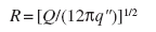 (Equation
9-8)
(Equation
9-8)
where:
q"
= Incident radiant heat
flux required for nonpiloted ignition, Btu/ft2
· s (W/m2).
Q = Heat release
from fire, Btu/s (kW).
R =
Separation distance from target to center of fuel package,
feet (m).
[F]
909.9.3 Heat-release assumptions. The analysis shall
make use of best available data from approved sources and
shall not be based on excessively stringent limitations
of combustible material.
[F]
909.9.4 Sprinkler effectiveness assumptions. A documented
engineering analysis shall be provided for conditions that
assume fire growth is halted at the time of sprinkler activation.
[F]
909.10 Equipment. Equipment including, but not limited
to, fans, ducts, automatic dampers and balance dampers, shall
be suitable for its intended use, suitable for the probable
exposure temperatures that the rational analysis indicates
and as approved by the fire code official.
[F]
909.10.1 Exhaust fans. Components of exhaust fans shall
be rated and certified by the manufacturer for the probable
temperature rise to which the components will be exposed.
This temperature rise shall be computed by:
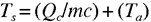 (Equation 9-9)
where:
c = Specific
heat of smoke at smoke layer temperature, Btu/lb°F (kJ/kg
· K).
m = Exhaust
rate, pounds per second (kg/s).
Qc = Convective heat
output of fire, Btu/s (kW).
Ta = Ambient
temperature, of (K).
Ts = Smoke
temperature, of (K).
Exception: Reduced Ts as calculated
based on the assurance of adequate dilution air.
[F]
909.10.2 Ducts. Duct materials and joints shall be capable
of withstanding the probable temperatures and pressures
to which they are exposed as determined in accordance with
Section 909.10.1. Ducts shall be constructed and supported
in accordance with the International Mechanical Code . Ducts
shall be leak tested to 1.5 times the maximum design pressure
in accordance with nationally accepted practices. Measured
leakage shall not exceed 5 percent of design flow. Results
of such testing shall be a part of the documentation procedure.
Ducts shall be supported directly from fire-resistance-rated
structural elements of the building by substantial, noncombustible
supports.
Exception: Flexible connections (for the purpose of vibration
isolation) complying with the International Mechanical Code,
that are constructed of approved fire-resistance-rated materials.
[F] 909.10.3 Equipment,
inlets and outlets. Equipment shall be located so as
to not expose uninvolved portions of the building to an
additional fire hazard. Outside air inlets shall be located
so as to minimize the potential for introducing smoke or
flame into the building. Exhaust outlets shall be so located
as to minimize reintroduction of smoke into the building
and to limit exposure of the building or adjacent buildings
to an additional fire hazard.
[F]
909.10.4 Automatic dampers. Automatic dampers, regardless
of the purpose for which they are installed within the smoke
control system, shall be listed and conform to the requirements
of approved, recognized standards.
[F]
909.10.5 Fans. In addition to other requirements, belt-driven
fans shall have 1.5 times the number of belts required for
the design duty, with the minimum number of belts being
two. Fans shall be selected for stable performance based
on normal temperature and, where applicable, elevated temperature.
Calculations and manufacturer's fan curves shall be part
of the documentation procedures. Fans shall be supported
and restrained by noncombustible devices in accordance with
the requirements of Chapter 16. Motors driving fans shall
not be operated beyond their nameplate horsepower (kilowatts),
as determined from measurement of actual current draw, and
shall have a minimum service factor of 1.15.
[F]
909.11 Power systems. The smoke control system shall be
supplied with two sources of power. Primary power shall be
from the normal building power system. Secondary power shall
be from an approved standby source complying with the ICC
Electrical Code. The standby power source and its transfer
switches shall be in a separate room from the normal power
transformers and switch gear and shall be enclosed in a room
constructed of not less than 1-hour fire barriers ventilated
directly to and from the exterior. Power distribution from
the two sources shall be by independent routes. Transfer to
full standby power shall be automatic and within 60 seconds
of failure of the primary power. The systems shall comply
with this code or the ICC Electrical Code.
[F]
909.11.1 Power sources and power surges. Elements of
the smoke management system relying on volatile memories
or the like shall be supplied with uninterruptable power
sources of sufficient duration to span a 15-minute primary
power interruption. Elements of the smoke management system
susceptible to power surges shall be suitably protected
by conditioners, suppressors or other approved means.
[F]
909.12 Detection and control systems. Fire detection systems
providing control input or output signals to mechanical smoke
control systems or elements thereof shall comply with the
requirements of Section 907. Such systems
shall be equipped with a control unit complying with UL 864
and listed as smoke control equipment. Control systems for
mechanical smoke control systems shall include provisions
for verification. Verification shall include positive confirmation
of actuation, testing, manual override, the presence of power
downstream of all disconnects and, through a preprogrammed
weekly test sequence, report abnormal conditions audibly,
visually and by printed report.
[F]
909.12.1 Wiring. In addition to meeting requirements
of the ICC Electrical Code, all wiring, regardless of voltage,
shall be fully enclosed within continuous raceways.
[F]
909.12.2 Activation. Smoke control systems shall be
activated in accordance with this section.
[F] 909.12.2.1 Pressurization, airflow or exhaust method.
Mechanical smoke control systems using the pressurization,
airflow or exhaust method shall have completely automatic
control.
[F] 909.12.2.2 Passive method. Passive smoke control
systems actuated by approved spot-type detectors listed
for releasing service shall be permitted.
[F]
909.12.3 Automatic control. Where completely automatic
control is required or used, the automatic-control sequences
shall be initiated from an appropriately zoned automatic
sprinkler system complying with Section
903.3.1.1, manual controls that are readily accessible
to the fire department and any smoke detectors required
by engineering analysis.
[F]
909.13 Control air tubing. Control air tubing shall be
of sufficient size to meet the required response times. Tubing
shall be flushed clean and dry prior to final connections
and shall be adequately supported and protected from damage.
Tubing passing through concrete or masonry shall be sleeved
and protected from abrasion and electrolytic action.
[F]
909.13.1 Materials. Control air tubing shall be hard
drawn copper, Type L, ACR in accordance with ASTM B 42,
ASTM B 43, ASTM B 68, ASTM B 88, ASTM B 2S1 and ASTM B 280.
Fittings shall be wrought copper or brass, solder type,
in accordance with ASME B 16.18 or ASME B 16.22. Changes
in direction shall be made with appropriate tool bends.
Brass compression-type fittings shall be used at final connection
to devices; other joints shall be brazed using a BCuP5 brazing
alloy with solidus above 1,100 °F (S93°C) and liquids below
1,500 °F (816°C). Brazing flux shall be used on copper-to-brass
joints only.
Exception: Nonmetallic tubing used within control panels
and at the final connection to devices, provided that all
of the following conditions are met:
1. Tubing shall be listed by an approved agency for flame
and smoke characteristics.
2. Tubing and connected devices shall be completely
enclosed within galvanized or paint-grade steel enclosure
of not less than 0.030 inch (0.76 mm) (No. 22 galvanized
sheet gage) thickness. Entry to the enclosure shall be
by copper tubing with a protective grommet of neoprene
or teflon or by suitable brass compression to male-barbed
adapter.
3.
Tubing shall be identified by appropriately documented
coding.
4. Tubing shall be neatly tied and supported within enclosure.
Tubing bridging cabinet and door or moveable device shall
be of sufficient length to avoid tension and excessive
stress. Tubing shall be protected against abrasion. Tubing
serving devices on doors shall be fastened along hinges.
[F]
909.13.2 Isolation from other functions. Control tubing
serving other than smoke control functions shall be isolated
by automatic isolation valves or shall be an independent
system.
[F]
909.13.3 Testing. Control air tubing shall be tested
at three times the operating pressure for not less than
30 minutes without any noticeable loss in gauge pressure
prior to final connection to devices.
[F]
909.14 Marking and identification. The detection and control
systems shall be clearly marked at all junctions, accesses
and terminations.
[F]
909.15 Control diagrams. Identical control diagrams showing
all devices in the system and identifying their location and
function shall be maintained current and kept on file with
the fire code official, the fire department and in the fire
command center in a format and manner approved by the fire
chief.
[F] 909.16 Fire-fighter's
smoke control panel. A fire-fighter's smoke control panel
for fire department emergency response purposes only shall
be provided and shall include manual control or override of
automatic control for mechanical smoke control systems. The
panel shall be located in a fire command center complying
with Section 911 in highrise buildings
or buildings with smoke-protected assembly seating. In all
other buildings, the fire-fighter's smoke control panel shall
be installed in an approved location adjacent to the fire
alarm control panel. The fire-fighter's smoke control panel
shall comply with Sections 909.16.1 through 909.16.3.
[F]
909.16.1 Smoke control systems. Fans within the building
shall be shown on the fire- fighter's control panel. A clear
indication of the direction of airflow and the relationship
of components shall be displayed. Status indicators shall
be provided for all smoke control equipment, annunciated
by fan and zone, and by pilot-lamp-type indicators as follows:
1.
Fans, dampers and other operating equipment in their normal
status-WHITE.
2.
Fans, dampers and other operating equipment in their off
or closed status-RED.
3.
Fans, dampers and other operating equipment in their on
or open status-GREEN.
4. Fans, dampers and other
operating equipment in a fault status-YELLOW/AMBER.
[F]
909.16.2 Smoke control panel. The fire-fighter's control
panel shall provide control capability over the complete
smoke-control system equipment within the building as follows:
1.ON-AUTO-OFF control
over each individual piece of operating smoke control
equipment that can also be controlled from other sources
within the building. This includes stairway pressurization
fans; smoke exhaust fans; supply, return and exhaust fans;
elevator shaft fans and other operating equipment used
or intended for smoke control purposes.
2.OPEN-AUTO-CLOSE
control over individual dampers relating to smoke
control and that are also controlled from other sources
within the building.
3.ON-OFF
or OPEN-CLOSE control over smoke control and other
critical equipment associated with a fire or smoke emergency
and that can only be controlled from the fire-fighter's
control panel.
Exceptions:
1.Complex systems, where approved, where the controls
and indicators are combined to control and indicate all
elements of a single smoke zone as a unit.
2.Complex systems, where approved, where the control is
accomplished by computer interface using approved, plain
English commands.
[F]
909.16.3 Control action and priorities. The firefighter's
control panel actions shall be as follows:
1.ON-OFF
and OPEN-CLOSE control actions shall have the highest
priority of any control point within the building. Once
issued from the fire-fighter' s control panel, no automatic
or manual control from any other control point within
the building shall contradict the control action. Where
automatic means are provided to interrupt normal, nonemergency
equipment operation or produce a specific result to safeguard
the building or equipment (i.e., duct freezes tats, duct
smoke detectors, high-temperature cutouts, temperature-actuated
linkage and similar devices), such means shall be capable
of being overridden by the fire- fighter's control panel.
The last control action as indicated by each fire-fighter's
control panel switch position shall prevail. In no case
shall control actions require the smoke control system
to assume more than one configuration at anyone time.
Exception: Power disconnects required by the ICC Electrical
Code.
2.Only
the AUTO position of each three-position fire-fighter's
control panel switch shall allow automatic or manual control
action from other control points within the building.
The AUTO position shall be the NORMAL, nonemergency,
building control position. Where a fire- fighter's control
panel is in the AUTO position, the actual status
of the device (on, off, open, closed) shall continue to
be indicated by the status indicator described above.
When directed by an automatic signal to assume an emergency
condition, the NORMAL position shall become the
emergency condition for that device or group of devices
within the zone. In no case shall control actions require
the smoke control system to assume more than one configuration
at anyone time.
[F]
909.17 System response time. Smoke-control system activation
shall be initiated immediately after receipt of an appropriate
automatic or manual activation command. Smoke control systems
shall activate individual components (such as dampers and
fans) in the sequence necessary to prevent physical damage
to the fans, dampers, ducts and other equipment. For purposes
of smoke control, the fire-fighter's control panel response
time shall be the same for automatic or manual smoke control
action initiated from any other building control point. The
total response time, including that necessary for detection,
shutdown of operating equipment and smoke control system startup,
shall allow for full operational mode to be achieved before
the conditions in the space exceed the design smoke condition.
The system response time for each component and their sequential
relationships shall be detailed in the required rational analysis
and verification of their installed condition reported in
the required final report.
[F]
909.18 Acceptance testing. Devices, equipment, components
and sequences shall be individually tested. These tests, in
addition to those required by other provisions of this code,
shall consist of determination of function, sequence and,
where applicable, capacity of their installed condition.
[F]
909.18.1 Detection devices. Smoke or fire detectors
that are a part of a smoke control system shall be tested
in accordance with Chapter 9 in their installed condition.
When applicable, this testing shall include verification
of airflow in both minimum and maximum conditions.
[F] 909.18.2 Ducts. Ducts that are part of a smoke control
system shall be traversed using generally accepted practices
to determine actual air quantities.
[F] 909.18.3 Dampers. Dampers shall be tested for function
in their installed condition.
[F]
909.18.4 Inlets and outlets. Inlets and outlets shall
be read using generally accepted practices to determine
air quantities.
[F]
909.18.5 Fans. Fans shall be examined for correct rotation.
Measurements of voltage, amperage, revolutions per minute
(rpm) and belt tension shall be made.
[F]
909.18.6 Smoke barriers. Measurements using inclined
manometers or other approved calibrated measuring devices
shall be made of the pressure differences across smoke barriers.
Such measurements shall be conducted for each possible smoke
control condition.
[F]
909.18.7 Controls. Each smoke zone, equipped with an
automatic-initiation device, shall be put into operation
by the actuation of one such device. Each additional device
within the zone shall be verified to cause the same sequence
without requiring the operation of fan motors in order to
prevent damage. Control sequences shall be verified throughout
the system, including verification of override from the
fire-fighter's control panel and simulation of standby power
conditions.
[F]
909.18.8 Special inspections for smoke control. Smoke
control systems shall be tested by a special inspector.
[F] 909.18.8.1 Scope of testing. Special inspections
shall be conducted in accordance with the following:
1.
During erection of ductwork and prior to concealment
for the purposes of leakage testing and recording of
device location.
2.
Prior to occupancy and after sufficient completion for
the purposes of pressure-difference testing, flow measurements,
and detection and control verification.
[F]
909.18.8.2 Qualifications. Special inspection agencies
for smoke control shall have expertise in fire protection
engineering, mechanical engineering and certification
as air balancers.
[F]
909.18.8.3 Reports. A complete report of testing shall
be prepared by the special inspector or special inspection
agency. The report shall include identification of all
devices by manufacturer, nameplate data, design values,
measured values and identification tag or mark. The report
shall be reviewed by the responsible registered design
professional and, when satisfied that the design intent
has been achieved, the responsible registered design professional
shall seal, sign and date the report.
[F]
909.18.8.3.1 Report filing. A copy of the final
report shall be filed with the fire code official and
an identical copy shall be maintained in an approved
location at the building.
[F]
909.18.9 Identification and documentation. Charts, drawings
and other documents identifying and locating each component
of the smoke control system, and describing its proper function
and maintenance requirements, shall be maintained on file
at the building as an attachment to the report required
by Section 909.18.8.3. Devices shall have an approved identifying
tag or mark on them consistent with the other required documentation
and shall be dated indicating the last time they were successfully
tested and by whom.
[F]
909.19 System acceptance. Buildings, or portions thereof,
required by this code to comply with this section shall not
be issued a certificate of occupancy until such time that
the fire I code official determines that the provisions of
this section have been fully complied with and that the fire
department has received satisfactory instruction on the operation,
both automatic and manual, of the system.
Exception: In buildings of phased construction, a temporary
certificate of occupancy, as approved by the fire code official,
shall be allowed provided that those portions of the building
to be occupied meet the requirements of this section and that
the remainder does not pose a significant hazard to the safety
of the proposed occupants or adjacent buildings.
909.20
Smokeproof enclosures. Where required by
Section 1020.1.7, a smokeproof enclosure shall be constructed
in accordance with this section. A smokeproof enclosure shall
consist of an enclosed interior exit stairway that conforms
to Section 1020.1 and an open exterior
balcony or ventilated vestibule meeting the requirements of
this section. Where access to the roof is required by the
International Fire Code, such access shall be from the smokeproof
enclosure where a smokeproof enclosure is required.
909.20.1 Access. Access to the stair shall be by way
of a vestibule or an open exterior balcony. The minimum
dimension of the vestibule shall not be less than the required
width of the corridor leading to the vestibule but shall
not have a width of less than 44 inches (1118 mm) and shall
not have a length of less than 72 inches (1829 mm) in the
direction of egress travel.
909.20.2 Construction. The smokeproof enclosure shall
be separated from the remainder of the building by not less
than a 2-hour fire barrier without openings other than the
required means of egress doors. The vestibule shall be separated
from the stairway by not less than a 2-hour fire barrier.
The open exterior balcony shall be constructed in accordance
with the fire-resistance-rating requirements for floor construction.
909.20.2.1
Door closers. Doors in a smokeproof enclosure shall
be self- or automatic closing by actuation of a smoke
detector installed at the floor-side entrance to the smokeproof
enclosure. The actuation of the smoke detector on any
door shall activate the closing devices on all doors in
the smokeproof enclosure at all levels. Smoke detectors
shall be installed in accordance with Section
907.10.
909.20.3
Natural ventilation alternative. The provisions of Sections
909.20.3.1 through 909.20.3.3 shall apply to ventilation
of smokeproof enclosures by natural means.
909.20.3.1 Balcony doors. Where access to the stairway
is by way of an open exterior balcony, the door assembly
into the enclosure shall be a fire door assembly in accordance
with Section 715.4.
909.20.3.2 Vestibule doors. Where access to the
stairway is by way of a vestibule, the door assembly into
the vestibule shall be a fire door complying with Section
715.4. The door assembly from the vestibule to the
stairway shall have not less than a 20-minute fire protection
rating complying with Section 715.4.
909.20.3.3 Vestibule ventilation. Each vestibule
shall have a minimum net area of 16 square feet (1.5 m2)
of opening in a wall facing an outer court, yard or public
way that is at least 20 feet (6096 mm) in width.
909.20.4 Mechanical ventilation alternative. The provisions
of Sections 909.20.4.1 through 909.20.4.4 shall apply to
ventilation of smokeproof enclosures by mechanical means.
909.20.4.1
Vestibule doors. The door assembly from the building
into the vestibule shall be a fire door assembly complying
with Section 715.4.3. The door
assembly from the vestibule to the stairway shall not
have less than a 20-minute fire protection rating and
meet the requirements for a smoke door assembly in accordance
with Section 715.4.3. The door
shall be installed in accordance with NFPA 105.
909.20.4.2
Vestibule ventilation. The vestibule shall be supplied
with not less than one air change per minute and the exhaust
shall not be less than 150 percent of supply. Supply air
shall enter and exhaust air shall discharge from the vestibule
through separate, tightly constructed ducts used only
for that purpose. Supply air shall enter the vestibule
within 6 inches (152 mm) of the floor level. The top of
the exhaust register shall be located at the top of the
smoke trap but not more than 6 inches (152 mm) down from
the top of the trap, and shall be entirely within the
smoke trap area. Doors in the open position shall not
obstruct duct openings. Duct openings with controlling
dampers are permitted where necessary to meet the design
requirements, but dampers are not otherwise required.
909.20.4.2.1
Engineered ventilation system. Where a specially
engineered system is used, the system shall exhaust
a quantity of air equal to not less than 90 air changes
per hour from any vestibule in the emergency operation
mode and shall be sized to handle three vestibules simultaneously.
Smoke detectors shall be located at the floor-side entrance
to each vestibule and shall activate the system for
the affected vestibule. Smoke detectors shall be installed
in accordance with Section 907.10.
909.20.4.3 Smoke trap. The vestibule ceiling shall
be at least 20 inches (508 mm) higher than the door opening
into the vestibule to serve as a smoke and heat trap and
to provide an upward-moving air column. The height shall
not be decreased unless approved and justified by design
and test.
909.20.4.4
Stair shaft air movement system. The stair shaft shall
be provided with a dampered relief opening and supplied
with sufficient air to maintain a minimum positive pressure
of 0.10 inch of water (25 Pa) in the shaft relative to
the vestibule with all doors closed.
909.20.5 Stair pressurization
alternative. Where the building is equipped throughout
with an automatic sprinkler system in accordance with Section
903.3.1.1, the vestibule is not required, provided that
interior exit stairways are pressurized to a minimum of
0.15 inch of water (37 Pa) and a maximum of 0.35 inch of
water (87 Pa) in the shaft relative to the building measured
with all stairway doors closed under maximum anticipated
stack pressures.
909.20.6 Ventilating equipment.
The activation of ventilating equipment required by the
alternatives in Sections 909.20.4 and 909.20.5 shall be
by smoke detectors installed at each floor level at an approved
location at the entrance to the smokeproof enclosure. When
the closing device for the stair shaft and vestibule doors
is activated by smoke detection or power failure, the mechanical
equipment shall activate and operate at the required performance
levels. Smoke detectors shall be installed in accordance
with Section 907.10.
909.20.6.1
Ventilation systems. Smokeproof enclosure ventilation
systems shall be independent of other building ventilation
systems. The equipment and ductwork shall comply with
one of the following:
1.
Equipment and ductwork shall be located exterior to
the building and directly connected to the smokeproof
enclosure or connected to the smokeproof enclosure by
ductwork enclosed by 2-hour fire barriers.
2.
Equipment and ductwork shall be located within the smokeproof
enclosure with intake or exhaust directly from and to
the outside or through ductwork enclosed by 2-hour fire
barriers.
3.
Equipment and ductwork shall be located within the building
if separated from the remainder of the building, including
other mechanical equipment, by 2-hour fire barriers.
909.20.6.2 Standby power. Mechanical vestibule
and stair shaft ventilation systems and automatic fire
detection systems shall be powered by an approved standby
power system conforming to Section
403.10.1 and Chapter 27.
909.20.6.3 Acceptance and testing. Before the mechanical
equipment is approved, the system shall be tested in the
presence of the building official to confirm that the
system is operating in compliance with these requirements.
|