| SECTION 1609 WIND LOADS
1609.1 Applications. Buildings,
structures and parts thereof shall be designed to withstand
the minimum wind loads prescribed herein. Decreases in wind
loads shall not be made for the effect of shielding by other
structures.
1609.1.1 Determination of
wind loads. Wind loads on every building or structure
shall be determined in accordance with Chapter 6 of ASCE
7. The type of opening protection required, the basic wind
speed and the exposure category for a site is permitted
to be determined in accordance with Section 1609 or ASCE
7.Wind shall be assumed to come from any horizontal direction
and wind pressures shall be assumed to act normal to the
surface considered.
Exceptions:
1. Subject to the limitations
of Section 1609.1.1.1, the provisions of SBCCI SSTD 10 shall
be permitted for applicable Group R-2 and R-3 buildings.
2. Subject to the limitations
of Section 1609.1.1.1, residential structures using the
provisions of the AF&PA WFCM.
3. Designs using NAAMM FP 1001.
4. Designs using TIA/EIA-222
for antenna-supporting structures and antennas.
1609.1.1.1 Applicability.
The provisions of SSTD 10 are applicable only to buildings
located within Exposure B or C as defined in Section 1609.4.
The provisions of SBCCI SSTD 10 and the AF&PA WFCM
shall not apply to buildings sited on the upper half of
an isolated hill, ridge or escarpment meeting the following
conditions:
1. The hill, ridge or escarpment
is 60 feet (18 288 mm) or higher if located in Exposure
B or 30 feet (9144 mm) or higher if located in Exposure
C;
2. The maximum average
slope of the hill exceeds 10 percent; and
3. The hill, ridge or escarpment
is unobstructed upwind by other such topographic features
for a distance from the high point of 50 times the height
of the hill or 1 mile (1.61 km), whichever is greater.
1609.1.2 Protection of openings.
In wind-borne debris regions, glazing in buildings shall
be impact-resistant or protected with an impact-resistant
covering meeting the requirements of an approved impact-resisting
standard or ASTM E 1996 and ASTM E 1886 referenced therein
as follows:
1. Glazed openings located
within 30 feet (9144 mm) of grade shall meet the requirements
of the Large Missile Test of ASTM E 1996.
2. Glazed openings located
more than 30 feet (9144 mm) above grade shall meet the
provisions of the Small Missile Test of ASTM E 1996.
Exceptions:
1. Wood structural panels with
a minimum thickness of 7/16 inch (11.1
mm) and maximum panel span of 8 feet (2438 mm) shall be
permitted for opening protection in one- and two-story buildings.
Panels shall be precut so that they shall be attached to
the framing surrounding the opening containing the product
with the glazed opening. Panels shall be secured with the
attachment hardware provided. Attachments shall be designed
to resist the components and cladding loads determined in
accordance with the provisions of ASCE 7. Attachment in
accordance with Table 1609.1.2
is permitted for buildings with a mean roof height of 33
feet (10 058 mm) or less where wind speeds do not exceed
130 mph (57.2 m/s).
2. Glazing in Occupancy Category
I buildings as defined in Section 1604.5,
including greenhouses that are occupied for growing plants
on a production or research basis, without public access
shall be permitted to be unprotected.
3. Glazing in Occupancy Category
II, III or IV buildings located over 60 feet (18 288 mm)
above the ground and over 30 feet (9144 mm) above aggregate
surface roofs located within 1,500 feet (458 m) of the building
shall be permitted to be unprotected.
1609.1.2.1 Louvers.
Louvers protecting intake and exhaust ventilation ducts
not assumed to be open that are located within 30 feet
(9144 mm) of grade shall meet requirements of an approved
impact-resisting standard or the Large Missile Test of
ASTM E 1996.
1609.2 Definitions. The
following words and terms shall, for the purposes of Section
1609, have the meanings shown herein.
HURRICANE-PRONE REGIONS.
Areas vulnerable to hurricanes defined as:
1. The U. S. Atlantic Ocean
and Gulf of Mexico coasts where the basic wind speed is
greater than 90 mph (40 m/s) and
2. Hawaii, Puerto Rico, Guam,
Virgin Islands and American Samoa.
WIND-BORNE DEBRIS REGION.
Portions of hurricane- prone regions that are within 1 mile
(1.61 km) of the coastal mean high water line where the basic
wind speed is 110 mph (48 m/s) or greater; or portions of
hurricane-prone regions where the basic wind speed is 120
mph (53 m/s) or greater; or Hawaii.
1609.3 Basic wind speed.
The basic wind speed, in mph, for the determination of the
wind loads shall be determined by Figure
1609. Basic wind speed for the special wind regions indicated,
near mountainous terrain and near gorges shall be in accordance
with local jurisdiction requirements. Basic wind speeds determined
by the local jurisdiction shall be in accordance with Section
6.5.4 of ASCE 7. In nonhurricane-prone regions, when the
basic wind speed is estimated from regional climatic data,
the basic wind speed shall be not less than the wind speed
associated with an annual probability of 0.02 (50-year mean
recurrence interval), and the estimate shall be adjusted for
equivalence to a 3-second gust wind speed at 33 feet (10 m)
above ground in Exposure Category C. The data analysis shall
be performed in accordance with Section
6.5.4.2 of ASCE 7.
1609.3.1 Wind speed conversion.
When required, the 3-second gust basic wind speeds of Figure
1609 shall be converted to fastest-mile wind speeds,
Vfm, using Table 1609.3.1
or Equation 16-34.

where:
V3S = 3-second
gust basic wind speed from Figure
1609.
1609.4 Exposure category.
For each wind direction considered, an exposure category
that adequately reflects the characteristics of ground surface
irregularities shall be determined for the site at which the
building or structure is to be constructed. Account shall
be taken of variations in ground surface roughness that arise
from natural topography and vegetation as well as from constructed
features.
1609.4.1 Wind directions
and sectors. For each selected wind direction at which
the wind loads are to be evaluated, the exposure of the
building or structure shall be determined for the two upwind
sectors extending 45 degrees (0.79 rad) either side of the
selected wind direction. The exposures in these two sectors
shall be determined in accordance with Sections 1609.4.2
and 1609.4.3 and the exposure resulting in the highest wind
loads shall be used to represent winds from that direction.
1609.4.2 Surface roughness
categories. A ground surface roughness within each 45-degree
(0.79 rad) sector shall be determined for a distance upwind
of the site as defined in Section 1609.4.3 from the categories
defined below, for the purpose of assigning an exposure
category as defined in Section 1609.4.3. Surface Roughness
B. Urban and suburban areas, wooded areas or other terrain
with numerous closely spaced obstructions having the size
of single-family dwellings or larger. Surface Roughness
C. Open terrain with scattered obstructions having heights
generally less than 30 feet (9144 mm). This category includes
flat open country, grasslands, and all water surfaces in
hurricane-prone regions. Surface Roughness D. Flat, unobstructed
areas and water surfaces outside hurricane-prone regions.
This category includes smooth mud flats, salt flats and
unbroken ice.
1609.4.3 Exposure categories.
An exposure category shall be determined in accordance with
the following:
Exposure B. Exposure
B shall apply where the ground surface roughness condition,
as defined by Surface Roughness B, prevails in the upwind
direction for a distance of at least 2,600 feet (792 m)
or 20 times the height of the building, whichever is greater.
Exception: For buildings
whose mean roof height is less than or equal to 30 feet
(9144 mm), the upwind distance is permitted to be reduced
to 1,500 feet (457 m).
Exposure C. Exposure
C shall apply for all cases where Exposures B or D do
not apply.
Exposure D. Exposure
D shall apply where the ground surface roughness, as defined
by Surface Roughness D, prevails in the upwind direction
for a distance of at least 5,000 feet (1524 m) or 20 times
the height of the building, whichever is greater. Exposure
D shall extend inland from the shoreline for a distance
of 600 feet (183 m) or 20 times the height of the building,
whichever is greater.
1609.5 Roof systems.
1609.5.1 Roof deck.
The roof deck shall be designed to withstand the wind pressures
determined in accordance with ASCE 7.
1609.5.2 Roof coverings.
Roof coverings shall comply with Section 1609.5.1.
Exception: Rigid tile
roof coverings that are air permeable and installed over a
roof deck complying with Section 1609.5.1 are permitted to
be designed in accordance with Section 1609.5.3. Asphalt shingles
installed over a roof deck complying with Section 1609.5.1
shall be tested to determine the resistance of the sealant
to uplift forces using ASTM D 6381. Asphalt shingles installed
over a roof deck complying with Section 1609.5.1 are permitted
to be designed using UL 2390 to determine appropriate uplift
and force coefficients applied to the shingle.
1609.5.3 Rigid tile.
Wind loads on rigid tile roof coverings shall be determined
in accordance with the following equation:
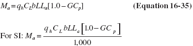
where:
b = Exposed width, feet (mm)
of the roof tile.
CL = Lift coefficient.
The lift coefficient for concrete and clay tile shall
be 0.2 or shall be determined by test in accordance with
Section 1715.2.
GCp = Roof pressure
coefficient for each applicable roof zone determined from
Chapter 6 of ASCE 7. Roof coefficients shall not be adjusted
for internal pressure.
L = Length, feet (mm) of
the roof tile.
La = Moment arm,
feet (mm) from the axis of rotation to the point of uplift
on the roof tile. The point of uplift shall be taken at
0.76L from the head of the tile and the middle of the
exposed width. For roof tiles with nails or screws (with
or without a tail clip), the axis of rotation shall be
taken as the head of the tile for direct deck application
or as the top edge of the batten for battened applications.
For roof tiles fastened only by a nail or screw along
the side of the tile, the axis of rotation shall be determined
by testing. For roof tiles installed with battens and
fastened only by a clip near the tail of the tile, the
moment arm shall be determined about the top edge of the
batten with consideration given for the point of rotation
of the tiles based on straight bond or broken bond and
the tile profile.
Ma = Aerodynamic
uplift moment, feet-pounds (N-mm) acting to raise the
tail of the tile.
qh = Wind velocity
pressure, psf (kN/m2) determined from Section
6.5.10 of ASCE 7. Concrete and clay roof tiles complying
with the following limitations shall be designed to withstand
the aerodynamic uplift moment as determined by this section.
1. The roof tiles shall
be either loose laid on battens, mechanically fastened,
mortar set or adhesive set.
2. The roof tiles shall
be installed on solid sheathing which has been designed
as components and cladding.
3. An underlayment shall
be installed in accordance with Chapter 15.
4. The tile shall be single
lapped interlocking with a minimum head lap of not less
than 2 inches (51 mm).
5. The length of the tile
shall be between 1.0 and 1.75 feet (305 mm and 533 mm).
6. The exposed width of
the tile shall be between 0.67 and 1.25 feet (204 mm
and 381 mm).
7. The maximum thickness
of the tail of the tile shall not exceed 1.3 inches
(33 mm).
8. Roof tiles using mortar
set or adhesive set systems shall have at least two-thirds
of the tile’s area free of mortar or adhesive contact.
|