| SECTION 1613 EARTHQUAKE LOADS
1613.1 Scope. Every structure,
and portion thereof, including nonstructural components that
are permanently attached to structures and their supports
and attachments, shall be designed and constructed to resist
the effects of earthquake motions in accordance with ASCE
7, excluding Chapter 14 and Appendix 11A. The seismic design
category for a structure is permitted to be determined in
accordance with Section 1613 or ASCE 7.
Exceptions:
1. Detached one- and two-family
dwellings, assigned to Seismic Design Category A, B or C,
or located where the mapped short-period spectral response
acceleration, SS, is less than 0.4 g.
2. The seismic-force-resisting
system of wood-frame buildings that conform to the provisions
of Section 2308 are not required
to be analyzed as specified in this section.
3. Agricultural storage structures
intended only for incidental human occupancy.
4. Structures that require
special consideration of their response characteristics
and environment that are not addressed by this code or ASCE
7 and for which other regulations provide seismic criteria,
such as vehicular bridges, electrical transmission towers,
hydraulic structures, buried utility lines and their appurtenances
and nuclear reactors.
1613.2 Definitions. The
following words and terms shall, for the purposes of this
section, have the meanings shown herein.
DESIGN EARTHQUAKE GROUND MOTION.
The earthquake ground motion that buildings and structures
are specifically proportioned to resist in Section 1613.
MAXIMUM CONSIDERED EARTHQUAKE
GROUND MOTION. The most severe earthquake effects considered
by this code.
MECHANICAL SYSTEMS. For
the purposes of determining seismic loads in ASCE 7, mechanical
systems shall include plumbing systems as specified therein.
ORTHOGONAL. To be in two
horizontal directions, at 90 degrees (1.57 rad) to each other.
SEISMIC DESIGN CATEGORY.
A classification assigned to a structure based on its occupancy
category and the severity of the design earthquake ground
motion at the site.
SEISMIC-FORCE-RESISTING SYSTEM.
That part of the structural system that has been considered
in the design to provide the required resistance to the prescribed
seismic forces.
SITE CLASS. A classification
assigned to a site based on the types of soils present and
their engineering properties as defined in Section 1613.5.2.
SITE COEFFICIENTS. The
values of Fa and Fv indicated in Tables
1613.5.3(1) and 1613.5.3(2),
respectively.
1613.3 Existing buildings.
Additions, alterations, modification, or change of occupancy
of existing buildings shall be in accordance with Sections
3403.2.3 and 3406.4.
1613.4 Special inspections.
Where required by Section 1705.3,
the statement of special inspections shall include the special
inspections required by Section 1705.3.1.
1613.5 Seismic ground motion
values. Seismic ground motion values shall be determined
in accordance with this section.
1613.5.1 Mapped acceleration
parameters. The parameters Ss and S1 shall be determined
from the 0.2 and 1-second spectral response accelerations
shown on Figures 1613.5(1)
through 1613.5(14).
Where S1 is less than or equal to 0.04 and Ss is less than
or equal to 0.15, the structure is permitted to be assigned
to Seismic Design Category A.
1613.5.2 Site class definitions.
Based on the site soil properties, the site shall be classified
as either Site Class A, B, C, D, E or F in accordance with
Table 1613.5.2. When the
soil properties are not known in sufficient detail to determine
the site class, Site Class D shall be used unless the building
official or geotechnical data determines that Site Class
E or F soil is likely to be present at the site.
1613.5.3 Site coefficients
and adjusted maximum considered earthquake spectral response
acceleration parameters. The maximum considered earthquake
spectral response acceleration for short periods, SMS,
and at 1-second period, SM1, adjusted for site
class effects shall be determined by Equations 16-37 and
16-38, respectively:
SMS =FaSs
(Equation 16-37)
SM1 =Fv
S1
(Equation 16-38)
where:
Fa = Site coefficient
defined in Table 1613.5.3(1).
Fv = Site coefficient
defined in Table 1613.5.3(2).
SS = The mapped
spectral accelerations for short periods as determined in
Section 1613.5.1.
S1 = The mapped
spectral accelerations for a 1-second period as determined
in Section 1613.5.1.
1613.5.4 Design spectral
response acceleration parameters. Five-percent damped
design spectral response acceleration at short periods,
SDS, and at 1-second period, SD1,
shall be determined from Equations 16-39 and 16-40, respectively:
 (Equation 16-39)
 (Equation 16-40)
where:
SMS = The maximum
considered earthquake spectral response accelerations for
short period as determined in Section 1613.5.3.
SM1 = The maximum
considered earthquake spectral response accelerations for
1-second period as determined in Section 1613.5.3.
1613.5.5 Site classification
for seismic design. Site classification for Site Class
C, D or E shall be determined from Table
1613.5.5. The notations presented below apply to the
upper 100 feet (30 480 mm) of the site profile. Profiles
containing distinctly different soil and/or rock layers
shall be subdivided into those layers designated by a number
that ranges from 1 to n at the bottom where there is a total
of n distinct layers in the upper 100 feet (30 480 mm).
The symbol i then refers to any one of the layers between
1 and n.
where:
vsi = The shear
wave velocity in feet per second (m/s).
di = The thickness
of any layer between 0 and 100 feet (30 480 mm).
where:
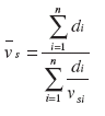 (Equation 16-41)
 = 100 feet (30 480 mm)
Ni is the Standard
Penetration Resistance (ASTM D 1586) not to exceed 100 blows/foot
(305 mm) as directly measured in the field without corrections.
When refusal is met for a rock layer, Ni shall be taken
as 100 blows/foot (305 mm).
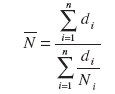 (Equation 16-42)
where:
Ni and di
in Equation 16-42 are for cohesionless soil, cohesive soil
and rock layers.
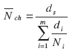 (Equation 16-43)
where:

Use di and Ni
for cohesionless soil layers only in Equation 16-43.
ds = The total thickness
of cohesionless soil layers in the top 100 feet (30 480
mm).
m = The number of cohesionless
soil layers in the top 100 feet (30 480 mm).
sui = The undrained
shear strength in psf (kPa), not to exceed 5,000 psf (240
kPa), ASTM D 2166 or D 2850.
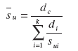 (Equation 16-44)
where:

dc = The total thickness
of cohesive soil layers in the top 100 feet (30 480 mm).
k = The number of cohesive
soil layers in the top 100 feet (30 480 mm).
PI = The plasticity index,
ASTM D 4318.
w = The moisture content in
percent, ASTM D 2216.
Where a site does not qualify
under the criteria for Site Class F and there is a total
thickness of soft clay greater than 10 feet (3048 mm) where
a soft clay layer is defined by: su < 500
psf (24 kPa), w≥ 40 percent, and PI > 20, it shall
be classified as Site Class E.
The shear wave velocity for
rock, Site Class B, shall be either measured on site or
estimated by a geotechnical engineer or engineering geologist/seismologist
for competent rock with moderate fracturing and weathering.
Softer and more highly fractured and weathered rock shall
either be measured on site for shear wave velocity or classified
as Site Class C.
The hard rock category, Site
Class A, shall be supported by shear wave velocity measurements
either on site or on profiles of the same rock type in the
same formation with an equal or greater degree of weathering
and fracturing. Where hard rock conditions are known to
be continuous to a depth of 100 feet (30 480 mm), surficial
shear wave velocity measurements are permitted to be extrapolated
to assess vs.
The rock categories, Site Classes
A and B, shall not be used if there is more than 10 feet
(3048 mm) of soil between the rock surface and the bottom
of the spread footing or mat foundation.
1613.5.5.1 Steps for classifying
a site.
1. Check for the four categories
of Site Class F requiring site-specific evaluation.
If the site corresponds to any of these categories,
classify the site as Site Class F and conduct a site-specific
evaluation.
2. Check for the existence
of a total thickness of soft clay > 10 feet (3048
mm) where a soft clay layer is defined by: su
< 500 psf (24 kPa), w ≥ 40 percent and PI >
20. If these criteria are satisfied, classify the site
as Site Class E.
3. Categorize the site
using one of the following three methods with vs
, N, and su and computed in all cases as
specified.
3.1. vs for
the top 100 feet (30 480 mm) (vs method).
3.2. Nch for
the top 100 feet (30 480 mm) (N method).
3.3. N for cohesionless
soil layers (PI < 20) in the top 100 feet (30 480
mm) and average, su for cohesive soil layers (PI >
20) in the top 100 feet (30 480 mm) ( su
method).
1613.5.6 Determination of
seismic design category. Occupancy Category I, II or
III structures located where the mapped spectral response
acceleration parameter at 1-second period, Sl,
is greater than or equal to 0.75 shall be assigned to Seismic
Design Category E. Occupancy Category IV structures located
where the mapped spectral response acceleration parameter
at 1-second period, S1, is greater than or equal to 0.75
shall be assigned to Seismic Design Category F. All other
structures shall be assigned to a seismic design category
based on their occupancy category and the design spectral
response acceleration coefficients, SDS and SD1,
determined in accordance with Section 1613.5.4 or the site-specific
procedures of ASCE 7. Each building and structure shall
be assigned to the more severe seismic design category in
accordance with Table 1613.5.6(1)
or 1613.5.6(2), irrespective
of the fundamental period of vibration of the structure,
T.
1613.5.6.1 Alternative
seismic design category determination. Where S1 is
less than 0.75, the seismic design category is permitted
to be determined from Table
1613.5.6(1) alone when all of the following apply:
1. In each of the two orthogonal
directions, the approximate fundamental period of the
structure, Ta, in each of the two orthogonal directions
determined in accordance with Section
12.8.2.1 of ASCE 7, is less than 0.8 Ts determined
in accordance with Section 11.4.5
of ASCE 7.
2. In each of the two orthogonal
directions, the fundamental period of the structure
used to calculate the story drift is less than Ts.
3. Equation 12.8-2 of ASCE
7 is used to determine the seismic response coefficient,
Cs.
4. The diaphragms are rigid
as defined in Section 12.3.1
in ASCE 7 or for diaphragms that are flexible, the distance
between vertical elements of the seismic-force-resisting
system does not exceed 40 feet (12 192 mm).
1613.5.6.2 Simplified
design procedure. Where the alternate simplified design
procedure of ASCE 7 is used, the seismic design category
shall be determined in accordance with ASCE 7.
1613.6 Alternatives to ASCE
7. The provisions of Section 1613.6 shall be permitted
as alternatives to the relevant provisions of ASCE 7.
1613.6.1 Assumption of flexible
diaphragm. Add the following text at the end of Section
12.3.1.1 of ASCE 7: Diaphragms constructed of wood structural
panels or untopped steel decking shall also be permitted
to be idealized as flexible, provided all of the following
conditions are met:
1. Toppings of concrete or
similar materials are not placed over wood structural
panel diaphragms except for nonstructural toppings no
greater than 11/2 inches (38 mm)
thick.
2. Each line of vertical
elements of the lateral- force-resisting system complies
with the allowable story drift of Table
12.12-1.
3. Vertical elements of the
lateral-force-resisting system are light-framed walls
sheathed with wood structural panels rated for shear resistance
or steel sheets.
4. Portions of wood structural
panel diaphragms that cantilever beyond the vertical elements
of the lateral- force-resisting system are designed in
accordance with Section 2305.2.5
of the International Building Code.
1613.6.2 Additional seismic-force-resisting
systems for seismically isolated structures. Add the
following exception to the end of
Section 17.5.4.2 of ASCE 7:
Exception: For isolated
structures designed in accordance with this standard, the
Structural System Limitations and the Building Height Limitations
in Table 12.2-1 for ordinary
steel concentrically braced frames (OCBFs) as defined in Chapter
11 and ordinary moment frames (OMFs) as defined in Chapter
11 are permitted to be taken as 160 feet (48 768 mm) for structures
assigned to Seismic Design Category D, E or F, provided that
the following conditions are satisfied:
1. The value of RI as defined
in Chapter 17 is taken as 1.
2. For OMFs and OCBFs, design
is in accordance with AISC 341.
|