| SECTION 2107 ALLOWABLE STRESS
DESIGN
2107.1 General. The design
of masonry structures using allowable stress design shall
comply with Section 2106 and the requirements
of Chapters 1 and 2 of ACI 530/ASCE 5/TMS 402 except as modified
by Sections 2107.2 through 2107.8.
2107.2 ACI 530/ASCE 5/TMS
402, Section 2.1.2, load combinations.
Delete Section 2.1.2.1.
2107.3 ACI 530/ASCE 5/TMS
402, Section 2.1.3, design strength.
Delete Sections 2.1.3.4 through
2.1.3.4.3.
2107.4 ACI 530/ASCE 5/TMS
402, Section 2.1.6, columns. Add the following text to
Section 2.1.6:
2.1.6.6 Light-frame construction.
Masonry columns used only to support light-frame roofs of
carports, porches, sheds or similar structures with a maximum
area of 450 square feet (41.8 m2) assigned to
Seismic Design Category A, B or Care permitted to be designed
and constructed as follows:
1. Concrete masonry materials
shall be in accordance with Section
2103.1 of the International Building Code. Clay or
shale masonry units shall be in accordance with Section
2103.2 of the International Building Code.
2. The nominal cross-sectional
dimension of columns shall not be less than 8 inches (203
mm).
3. Columns shall be reinforced
with not less than one No. 4 bar centered in each cell
of the column.
4. Columns shall be grouted
solid.
5. Columns shall not exceed
12 feet (3658 mm) in height.
6. Roofs shall be anchored
to the columns. Such anchorage shall be capable of resisting
the design loads specified in Chapter 16 of the International
Building Code.
7. Where such columns are
required to resist uplift loads, the columns shall be
anchored to their footings with two No. 4 bars extending
a minimum of 24 inches (610 mm) into the columns and bent
horizontally a minimum of 15 inches (381 mm) in opposite
directions into the footings. One of these bars is permitted
to be the reinforcing bar specified in Item 3 above. The
total weight of a column and its footing shall not be
less than 1.5 times the design uplift load.
2107.5 ACI 530/ASCE 5/TMS
402, Section 2.1.10.7.1.1, lap splices. Modify Section
2.1.10.7.1.1 as follows:
2.1.10.7.1.1 The minimum length
of lap splices for reinforcing bars in tension or compression,
ld, shall be
ld = 0.002dbfs
(Equation 21-2)
For SI: ld = 0.29dbfs
but not less than 12 inches
(305 mm). In no case shall the length of the lapped splice
be less than 40 bar diameters.
where:
db = Diameter of
reinforcement, inches (mm).
fs = Computed stress
in reinforcement due to design loads, psi (MPa).
In regions of moment where the
design tensile stresses in the reinforcement are greater than
80 percent of the allowable steel tension stress, Fs,
the lap length of splices shall be increased not less than
50 percent of the minimum required length. Other equivalent
means of stress transfer to accomplish the same 50 percent
increase shall be permitted. Where epoxy coated bars are used,
lap length shall be increased by 50 percent.
2107.6 ACI 530/ASCE 5/TMS
402, Section 2.1.10.7, splices of reinforcement. Modify
Section 2.1.10.7 as follows:
2.1.10.7 Splices of reinforcement.
Lap splices, welded splices or mechanical splices are permitted
in accordance with the provisions of this section. All welding
shall conform to AWS D1.4. Reinforcement larger than No.
9 (M #29) shall be spliced using mechanical connections
in accordance with Section 2.1.10.7.3.
2107.7 ACI 530/ASCE 5/TMS
402, Section 2.3.6, maximum bar size. Add the following
to Chapter 2:
2.3.6 Maximum bar size. The
bar diameter shall not exceed one-eighth of the nominal
wall thickness and shall not exceed one-quarter of the least
dimension of the cell, course or collar joint in which it
is placed.
2107.8 ACI 530/ASCE 5/TMS
402, Section 2.3.7, maximum reinforcement percentage.
Add the following text to Chapter 2:
2.3.7 Maximum reinforcement
percentage. Special reinforced masonry shear walls having
a shear span ratio, M/Vd, equal to or greater
than 1.0 and having an axial load, P, greater than 0.05
f mAn that are subjected to in-plane
forces shall have a maximum reinforcement ratio, ρmax,
not greater than that computed as follows:
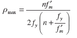 (Equation 21-3)
The maximum reinforcement ratio
does not apply in the out-of-plane direction.
|