| SECTION 2305 GENERAL DESIGN
REQUIREMENTS FOR LATERAL-FORCE-RESISTING SYSTEMS
2305.1 General. Structures
using wood shear walls and diaphragms to resist wind, seismic
and other lateral loads shall be designed and constructed
in accordance with the provisions of this section. Alternatively,
compliance with the AF&PA SDPWS shall be permitted subject
to the limitations therein and the limitations of this code.
2305.1.1 Shear resistance
based on principles of mechanics. Shear resistance of
diaphragms and shear walls are permitted to be calculated
by principles of mechanics using values of fastener strength
and sheathing shear resistance.
2305.1.2 Framing. Boundary
elements shall be provided to transmit tension and compression
forces. Perimeter members at openings shall be provided
and shall be detailed to distribute the shearing stresses.
Diaphragm and shear wall sheathing shall not be used to
splice boundary elements. Diaphragm chords and collectors
shall be placed in, or tangent to, the plane of the diaphragm
framing unless it can be demonstrated that the moments,
shears and deformations, considering eccentricities resulting
from other configurations can be tolerated without exceeding
the adjusted resistance and drift limits.
2305.1.2.1 Framing members.
Framing members shall be at least 2 inch (51 mm) nominal
width. In general, adjoining panel edges shall bear and
be attached to the framing members and butt along their
centerlines. Nails shall be placed not less than 3/8
inch (9.5 mm) from the panel edge, not more than 12 inches
(305 mm) apart along intermediate supports, and 6 inches
(152 mm) along panel edge bearings, and shall be firmly
driven into the framing members.
2305.1.3 Openings in shear
panels. Openings in shear panels that materially affect
their strength shall be fully detailed on the plans, and
shall have their edges adequately reinforced to transfer
all shearing stresses.
2305.1.4 Shear panel connections.
Positive connections and anchorages capable of resisting
the design forces shall be provided between the shear panel
and the attached components. In Seismic Design Category
D, E or F, the capacity of toenail connections shall not
be used when calculating lateral load resistance to transfer
lateral earthquake forces in excess of 150 pounds per foot
(2189 N/m) from diaphragms to shear walls, drag struts (collectors)
or other elements, or from shear walls to other elements.
2305.1.5 Wood members resisting
horizontal seismic forces contributed by masonry and concrete
walls. Wood shear walls, diaphragms, horizontal trusses
and other members shall not be used to resist horizontal
seismic forces contributed by masonry or concrete walls
in structures over one story in height.
Exceptions:
1. Wood floor and roof members
are permitted to be used in horizontal trusses and diaphragms
to resist horizontal seismic forces contributed by masonry
or concrete walls, provided such forces do not result
in torsional force distribution through the truss or diaphragm.
2. Wood structural panel
sheathed shear walls are permitted to be used to provide
resistance to seismic forces contributed by masonry or
concrete walls in two-story structures of masonry or concrete
walls, provided the following requirements are met:
2.1. Story-to-story wall
heights shall not exceed 12 feet (3658 mm).
2.2. Diaphragms shall not
be designed to transmit lateral forces by rotation and
shall not cantilever past the outermost supporting shear
wall.
2.3. Combined deflections
of diaphragms and shear walls shall not permit story
drift of supported masonry or concrete walls to exceed
the limit of Section 12.12.1
in ASCE 7.
2.4. Wood structural panel
sheathing in diaphragms shall have unsupported edges
blocked. Wood structural panel sheathing for both stories
of shear walls shall have unsupported edges blocked
and, for the lower story, shall have a minimum thickness
of 15/32 inch (11.9 mm).
2.5. There shall be no
out-of-plane horizontal offsets between the first and
second stories of wood structural panel shear walls.
2305.1.6 Wood members resisting
seismic forces from nonstructural concrete or masonry.
Wood members shall be permitted to resist horizontal seismic
forces from nonstructural concrete, masonry veneer or concrete
floors.
2305.2 Design of wood diaphragms.
2305.2.1 General. Wood
diaphragms are permitted to be used to resist horizontal
forces provided the deflection in the plane of the diaphragm,
as determined by calculations, tests or analogies drawn
there from, does not exceed the permissible deflection of
attached distributing or resisting elements. Connections
shall extend into the diaphragm a sufficient distance to
develop the force transferred into the diaphragm.
2305.2.2 Deflection.
Permissible deflection shall be that deflection up to which
the diaphragm and any attached distributing or resisting
element will maintain its structural integrity under design
load conditions, such that the resisting element will continue
to support design loads without danger to occupants of the
structure. Calculations for diaphragm deflection shall account
for the usual bending and shear components as well as any
other factors, such as nail deformation, which will contribute
to deflection.
The deflection ( ) of a blocked
wood structural panel diaphragm uniformly nailed throughout
is permitted to be calculated by using the following equation.
If not uniformly nailed, the constant 0.188 (For SI: 1/1627)
in the third term must be modified accordingly.
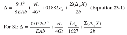
where:
A = Area of chord cross section,
in square inches (mm2).
b = Diaphragm width, in feet
(mm).
E = Elastic modulus of chords,
in pounds per square inch (N/mm2).
en = Nail or staple deformation,
in inches (mm) [see Table
2305.2.2(1)].
Gt = Panel rigidity through
the thickness, in pounds per inch (N/mm) of panel width
or depth [see Table 2305.2.2(2)].
L = Diaphragm length, in
feet (mm).
v = Maximum shear due to
design loads in the direction under consideration, in
pounds per linear foot (plf) (N/mm).
∆ = The calculated
deflection, in inches (mm).
Σ(∆cX)=
Sum of individual chord-splice slip values on both sides
of the diaphragm, each multiplied by its distance to the
nearest support.
2305.2.3 Diaphragm aspect
ratios. Size and shape of diaphragms shall be limited
as set forth in Table 2305.2.3.
2305.2.4 Construction.
Wood diaphragms shall be constructed of wood structural
panels manufactured with exterior glue and not less than
4 feet by 8 feet (1219mmby 2438 mm), except at boundaries
and changes in framing where minimum sheet dimension shall
be 24 inches (610 mm) unless all edges of the undersized
sheets are supported by and fastened to framing members
or blocking. Wood structural panel thickness for horizontal
diaphragms shall not be less than the valves set forth in
Tables 2304.7(3), 2304.7(4)
and 2304.7(5) for corresponding
joist spacing and loads.
2305.2.4.1 Seismic Design
Category F. Structures assigned to Seismic Design
Category F shall conform to the additional requirements
of this section. Wood structural panel sheathing used
for diaphragms and shear walls that are part of the seismic-force-resisting
system shall be applied directly to the framing members.
Exception: Wood structural
panel sheathing in a diaphragm is permitted to be fastened
over solid lumber planking or laminated decking, provided
the panel joints and lumber planking or laminated decking
joints do not coincide.
2305.2.5 Rigid diaphragms.
Design of structures with rigid diaphragms shall conform
to the structure configuration requirements of Section
12.3.2 of ASCE 7 and the horizontal shear distribution
requirements of Section 12.8.4
of ASCE 7. Open-front structures with rigid wood diaphragms
resulting in torsional force distribution are permitted,
provided the length, l, of the diaphragm normal to the open
side does not exceed 25 feet (7620 mm), the diaphragm sheathing
conforms to Section 2305.2.4 and the l/w ratio [as shown
in Figure 2305.2.5(1)]
is less than 1 for one-story structures or 0.67 for structures
over one story in height.
Exception: Where calculations
show that diaphragm deflections can be tolerated, the length,
l, normal to the open end is permitted to be increased to
a l/w ratio not greater than 1.5 where sheathed in compliance
with Section 2305.2.4 or to 1 where sheathed in compliance
with Section 2306.3.4 or 2306.3.5.
Rigid wood diaphragms are permitted to cantilever past the
outermost supporting shear wall (or other vertical resisting
element) a length, l, of not more than 25 feet (7620 mm) or
two-thirds of the diaphragm width, w, whichever is smaller.
Figure 2305.2.5(2) illustrates
the dimensions of l and w for a cantilevered diaphragm. Structures
with rigid wood diaphragms having a torsional irregularity
in accordance with Table 12.3-1,
Item 1, of ASCE 7 shall meet the following requirements: the
l/w ratio shall not exceed 1 for one-story structures
or 0.67 for structures over one story in height, where l
is the dimension parallel to the load direction for which
the irregularity exists.
Exception: Where calculations
demonstrate that the diaphragm deflections can be tolerated,
the width is permitted to be increased and the l/w
ratio is permitted to be increased to 1.5 where sheathed in
compliance with Section 2305.2.4 or 1 where sheathed in compliance
with Section 2306.3.4 or 2306.3.5.
2305.3 Design of wood shear
walls.
2305.3.1 General. Wood
shear walls are permitted to resist horizontal forces in
vertical distributing or resisting elements, provided the
deflection in the plane of the shear wall, as determined
by calculations, tests or analogies drawn there from, does
not exceed the more restrictive of the permissible deflection
of attached distributing or resisting elements or the drift
limits of Section 12.12.1 ofASCE7.
Shear wall sheathing other than wood structural panels shall
not be permitted in Seismic Design Category E or F (see
Section 1613).
2305.3.2 Deflection.
Permissible deflection shall be that deflection up to which
the shear wall and any attached distributing or resisting
element will maintain its structural integrity under design
load conditions, i.e., continue to support design loads
without danger to occupants of the structure. The deflection
(∆) of a blocked wood structural panel shear wall
uniformly fastened throughout is permitted to be calculated
by the use of the following equation:
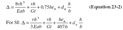
where:
A = Area of boundary element
cross section in square inches (mm2) (vertical
member at shear wall boundary).
b = Wall width, in feet
(mm).
da = Vertical
elongation of overturning anchorage (including fastener
slip, device elongation, anchor rod elongation, etc.)
at the design shear load (v).
E = Elastic modulus of
boundary element (vertical member at shear wall boundary),
in pounds per square inch (N/mm2).
en = Nail or staple deformation,
in inches (mm) [see Table
2305.2.2(1)].
Gt = Panel rigidity through
the thickness, in pounds per inch (N/mm) of panel width
or depth [see Table 305.2.2(2)].
h = Wall height, in feet
(mm).
v = Maximum shear due to
design loads at the top of the wall, in pounds per linear
foot (N/mm).
∆ = The calculated
deflection, in inches (mm).
2305.3.3 Construction.
Wood shear walls shall be constructed of wood structural
panels manufactured with exterior glue and not less than
4 feet by 8 feet (1219mmby 2438 mm), except at boundaries
and at changes in framing. All edges of all panels shall
be supported by and fastened to framing members or blocking.
Wood structural panel thickness for shear walls shall not
be less than set forth in Table
2304.6.1 for corresponding framing spacing and loads,
except that 1/4 inch (6.4 mm) is permitted
to be used where perpendicular loads permit.
2305.3.4 Shear wall aspect
ratios. Size and shape of shear walls, perforated shear
wall segments within perforated shear walls and wall piers
within shear walls that are designed for force transfer
around openings shall be limited as set forth in Table
2305.3.4. The height, h, and the width, w, shall be
determined in accordance with Sections 2305.3.5 through
2305.3.5.2 and 2305.3.6 through 2305.3.6.2, respectively.
2305.3.5 Shear wall height definition. The height
of a shear wall, h, shall be defined as:
1. The maximum clear height
from the top of the foundation to the bottom of the
diaphragm framing above; or
2. The maximum clear height
from the top of the diaphragm to the bottom of the diaphragm
framing above [see Figure
2305.3.5(a)].
2305.3.5.1 Perforated
shear wall segment height definition. The height of
a perforated shear wall segment, h, shall be defined as
specified in Section 2305.3.5 for shear walls.
2305.3.5.2 Force transfer
shear wall pier height definition. The height, h,
of a wall pier in a shear wall with openings designed
for force transfer around openings shall be defined as
the clear height of the pier at the side of an opening
[see Figure 2305.3.5(b)].
2305.3.6 Shear wall width
definition. The width of a shear wall, w, shall be defined
as the sheathed dimension of the shear wall in the direction
of application of force [see Figure
2305.3.5(a)].
2305.3.6.1 Perforated
shear wall segment width definition. The width of
a perforated shear wall segment, w, shall be defined as
the width of full-height sheathing adjacent to openings
in the perforated shear wall [see Figure
2305.3.5(a)].
2305.3.6.2 Force transfer
shear wall pier width definition. The width, w, of
a wall pier in a shear wall with openings designed for
force transfer around openings shall be defined as the
sheathed width of the pier at the side of an opening [see
Figure 2305.3.5(b)].
2305.3.7 Overturning restraint.
Where the dead load stabilizing moment in accordance
with Chapter 16 allowable stress design load combinations
is not sufficient to prevent uplift due to overturning moments
on the wall, an anchoring device shall be provided. Anchoring
devices shall maintain a continuous load path to the foundation.
2305.3.8 Shear walls with
openings. The provisions of this section shall apply
to the design of shear walls with openings. Where framing
and connections around the openings are designed for force
transfer around the openings, the provisions of Section
2305.3.8.1 shall apply. Where framing and connections around
the openings are not designed for force transfer around
the openings, the provisions of Section 2305.3.8.2 shall
apply.
2305.3.8.1 Force transfer
around openings. Where shear walls with openings are
designed for force transfer around the openings, the limitations
of Table 2305.3.4 shall
apply to the overall shear wall, including openings, and
to each wall pier at the side of an opening. Design for
force transfer shall be based on a rational analysis.
Detailing of boundary elements around the opening shall
be provided in accordance with the provisions of this
section[ see Figure 2305.3.5(b)].
2305.3.8.2 Perforated
shear walls. The provisions of Section 2305.3.8.2
shall be permitted to be used for the design of perforated
shear walls. For the determination of the height and width
of perforated shear wall segments, see Sections 2305.3.5.1
and 2305.3.6.1, respectively.
2305.3.8.2.1 Limitations.
The following limitations shall apply to the use of
Section 2305.3.8.2:
1. A perforated shear
wall segment shall be located at each end of a perforated
shear wall. Openings shall be permitted to occur beyond
the ends of the perforated shear wall, provided the
width of such openings is not be included in the width
of the perforated shear wall.
2. The allowable shear
set forth in Table 2306.4.1
shall not exceed 490 plf (7150 N/m).
3. Where out-of-plane
offsets occur, portions of the wall on each side of
the offset shall be considered as separate perforated
shear walls.
4. Collectors for shear
transfer shall be provided through the full length
of the perforated shear wall.
5. A perforated shear
wall shall have uniform top of wall and bottom of
wall elevations. Perfo-rated shear walls not having
uniform elevations shall be designed by other methods.
6. Perforated shear wall
height, h, shall not exceed 20 feet (6096 mm).
2305.3.8.2.2 Perforated
shear wall resistance. The resistance of a perforated
shear wall shall be calculated in accordance with the
following:
1. The percentage of
full-height sheathing shall be calculated as the
sum of the widths of perforated shear wall segments
divided by the total width of the perforated shear
wall, including openings.
2. The maximum opening
height shall be taken as the maximum opening clear
height. Where areas above and below an opening remain
unsheathed, the height of the opening shall be defined
as the height of the wall.
3. The unadjusted shear
resistance shall be the allowable shear set forth
in Table 2306.4.1
for height-to-width ratios of perforated shear wall
segments that do not exceed 2:1 for seismic forces
and 31/2:1 for other than
seismic forces. For seismic forces, where the height-to-width
ratio of any perforated shear wall segment used
in the calculation of the sum of the widths of perforated
shear wall segments, Li, is greater than 2:1 but
does not exceed 31/2:1, the
unadjusted shear resistance shall be multiplied
by 2 w/h.
4. The adjusted shear
resistance shall be calculated by multiplying the
unadjusted shear resistance by the shear resistance
adjustment factors of Table
2305.3.8.2. For intermediate percentages of
full-height sheathing, the values in Table
2305.3.8.2 are permitted to be interpolated.
5. The perforated shear
wall resistance shall be equal to the adjusted shear
resistance times the sum of the widths of the perforated
shear wall segments.
2305.3.8.2.3 Anchorage
and load path. Design of perforated shear wall anchorage
and load path shall conform to the requirements of Sections
2305.3.8.2.4 through 2305.3.8.2.8, or shall be calculated
using principles of mechanics. Except as modified by
these sections, wall framing, sheathing, sheathing attachment
and fastener schedules shall conform to the requirements
of Section 2305.2.4 and Table
2306.4.1.
2305.3.8.2.4 Uplift
anchorage at perforated shear wall ends. Anchorage
for uplift forces due to overturning shall be provided
at each end of the perforated shear wall. The uplift
anchorage shall conform to the requirements of Section
2305.3.7, except that for each story the minimum tension
chord uplift force, T, shall be calculated in accordance
with the following:

where:
T = Tension chord uplift
force, pounds (N).
V = Shear force in
perforated shear wall, pounds (N).
h = Perforated shear
wall height, feet (mm).
Co = Shear
resistance adjustment factor from Table
2305.3.8.2.
Li = Sum
of widths of perforated shear wall segments, feet
(mm).
2305.3.8.2.5 Anchorage
for in-plane shear. The unit shear force, v, transmitted
into the top of a perforated shear wall, out of the
base of the perforated shear wall at full height sheathing
and into collectors connecting shear wall segments shall
be calculated in accordance with the following:

where:
v = Unit shear force,
pounds per lineal feet (N/m).
V = Shear force in
perforated shear wall, pounds (N).
Co = Shear
resistance adjustment factor from Table
2305.3.8.2.
Li = Sum
of widths of perforated shear wall segments, feet
(mm).
2305.3.8.2.6 Uplift
anchorage between perforated shear wall ends. In
addition to the requirements of Section 2305.3.8.2.4,
perforated shear wall bottom plates at full- eight sheathing
shall be anchored for a uniform uplift force, t, equal
to the unit shear force, v, determined in Section 2305.3.8.2.5.
2305.3.8.2.7 Compression
chords. Each end of each perforated shear wall segment
shall be designed for a compression chord force, C,
equal to the tension chord uplift force, T, calculated
in Section 2305.3.8.2.4.
2305.3.8.2.8 Load path.
Load path. A load path to the foundation shall be
provided for each uplift force, T and t, for each shear
force, V and v, and for each compression chord force,
C. Elements resisting shear wall forces contributed
by multiple stories shall be designed for the sum of
forces contributed by each story.
2305.3.8.2.9 Deflection
of shear walls with openings. The controlling deflection
of a blocked shear wall with openings uniformly fastened
throughout shall be taken as the maximum individual
deflection of the shear wall segments calculated in
accordance with Section 2305.3.2, divided by the appropriate
shear resistance adjustment factors of Table
2305.3.8.2.
2305.3.9 Summing shear capacities.
The shear values for shear panels of different capacities
applied to the same side of the wall are not cumulative
except as allowed in Table
2306.4.1. The shear values for material of the same
type and capacity applied to both faces of the same wall
are cumulative. Where the material capacities are not equal,
the allowable shear shall be either two times the smaller
shear capacity or the capacity of the stronger side, whichever
is greater. Summing shear capacities of dissimilar materials
applied to opposite faces or to the same wall line is not
allowed.
Exception: For wind design,
the allowable shear capacity of shear wall segments sheathed
with a combination of wood structural panels and gypsum wallboard
on opposite faces, fiberboard structural sheathing and gypsum
wallboard on opposite faces or hardboard panel siding and
gypsum wallboard on opposite faces shall equal the sum of
the sheathing capacities of each face separately.
2305.3.10 Adhesives.
Adhesive attachment of shear wall sheathing is not permitted
as a substitute for mechanical fasteners, and shall not
be used in shear wall strength calculations alone, or in
combination with mechanical fasteners in Seismic Design
Category D, E or F.
2305.3.11 Sill plate size
and anchorage in Seismic Design Category D, E or F.
Anchor bolts for shear walls shall include steel plate washers,
a minimum of 0.229 inch by 3 inches by 3 inches (5.82 mm
by 76 mm by 76 mm) in size, between the sill plate and nut.
The hole in the plate washer is permitted to be diagonally
slotted with a width of up to 3/16
inch (4.76 mm) larger than the bolt diameter and a slot
length not to exceed 13/4 inches (44
mm), provided a standard cut washer is placed between the
plate washer and the nut. Sill plates resisting a design
load greater than 490 plf (7154 N/m) using load and resistance
factor design or 350 plf (5110 N/m) using allowable stress
design shall not be less than a 3-inch (76 mm) nominal member.
Where a single 3- inch (76 mm) nominal sill plate is used,
2- 20d box end nails shall be substituted for 2-16d common
end nails found in line 8 of Table
2304.9.1.
Exception: In shear walls
where the design load is greater than 490 plf (7151 N/m) but
less than 840 plf (12 264 N/m) using load and resistance factor
design or greater than 350 plf (5110 N/m) but less than 600
plf (8760 N/m) using allowable stress design, the sill plate
is permitted to be a 2-inch (51 mm) nominal member if the
sill plate is anchored by two times the number of bolts required
by design and 0.229-inch by 3-inch by 3-inch (5.82mmby 76mmby
76mm)platewashers are used.
|